I would like to introduce the concept of the Mobile Indexing Plate(MIB) that will allow an Amazing product like the ArcDroid to grow beyond the limitations of its work area. Mind you at the moment it is JUST a concept. Hopefully I will be able to laser cut or plasma cut an actual device and 3D print the pins soon and test the concept in real life until then enjoy.
The physical concept at the moment consists of 4 parts. An indexed plate with 10mm holes with number and letter cross references to the holes that is slightly larger than 660 by 380mm, two 10mm pins with easy to pull grip tops, and a zero reference point brass nub for the plasma cutter.
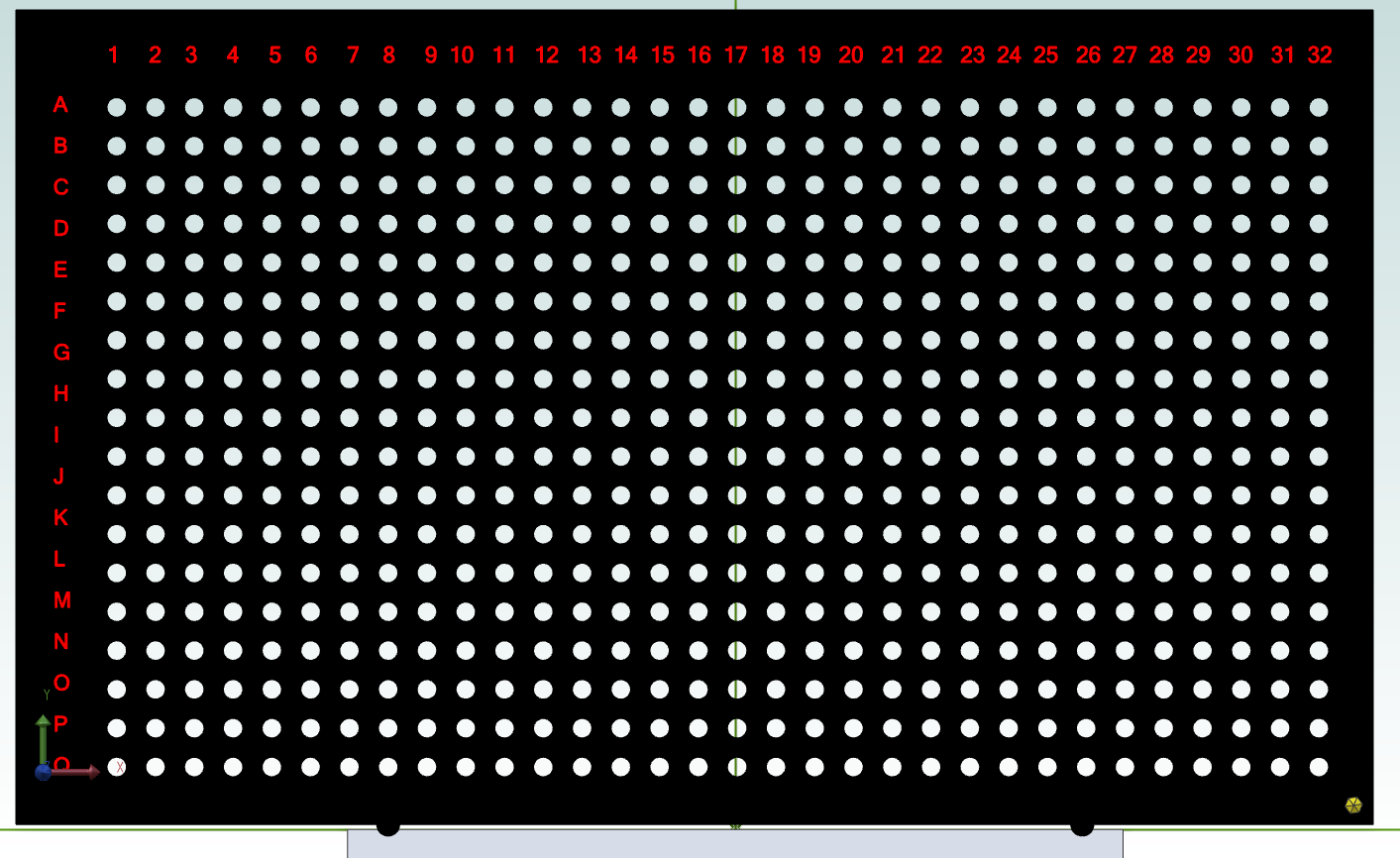

The add-on will allow you to extend the working area of the robot by having your plasma cutter cut 2 -10mm holes (preferable in a waste area) and use those holes as reference points to align the next location where the gcode can pick it up.
The secret sauce, such as it is; is the feature in your CAD software called “project to sketch”. At the moment this process is very manual in nature on the software side and requires some time upfront for the setup of the job. But once the software has done its job, the actual process of cutting should be pretty painless.

It roughly goes as so:
- You will install the posted gcode’s for the entire work area on your usb after your upfront software work described in detail below.

-
Now put your MIB on the work area roughly where it should go and butt your ArcDroid and clamp the ArcDroid down. Move the plasma cutter to the brass zero nub, lower the arm and set ZERO on your ArcDroid. While the placement of the first cut can be quite arbitrary in regards to it being “square”, remember that your entire design must actually fit on your material and if you skew it you might run out of material to cut, so best to do the software work with a model of your actual work material upfront!
-
Now remove the MIB and double check that you have Zero’ed the cutter on the brass nub and hit ZERO, load the first program and run it. It will then cut out that portion that it can reach and 2 additional 10 holes.

please ignore the red dots in this pix above for now but below counts!

- Now place the MIB in the next location and put in the pegs at the appropriate letter/number hole for cut 2. This will align your arc droid for the next cut. Clamp your arcdroid down, again zero on the brass nub, and load and dry run cut 2. Ensure it seems to be picking up where you left off and matches your cuts. If not you might have flubbed the software at this point but you can figure out where you went wrong and recover without wasting material.
- Assuming it cut fine, then the second run will also cut two new holes for the next run to reference too. Repeat step 4 until you have run through all your programs and your piece should be cut!
The Software Process
So I use Alibre to design all my parts and so am very familiar with it and like the idea of staying in a single software for the design part ( also it is dirt cheap and has a perpetual license and this procedure should be useable even with the lowest level product) Now I don’t know Fusion 360 very well but I do see it has a “project to sketch” feature, and so with some work is should be possible to use that for more than just the CAM (gcode post part). I still need to use Fusion 360 CAM myself to post fyi.
.
Ok let’s get started by describing the process below:

- I first create a panel that matches my work material in dimensions. This allows me to use an arbitrary shaped piece of metal and ensure that my indexing will happen within the work piece. In this case it’s a simple 1200 by 1200mm piece. I then paste in the DXF file and arrange it on the piece. For the concept, I made NO attempt to nest the parts as I wanted a large area to work with.

- I then did an extrude cut through the piece to help me see better for the next steps.

please ignore the red pins they should not be there at this point
- Next I did a duplicate of the ArcDroid and MIB assembly and roughly arranged them around the piece changing orientation to fully cover the cut area that will be needed. In this case you can see I needed 5 moves of the Assembly to fully cover the design area. (note: i probably didn’t if I had planned better and choose angles instead of 90 degree orientations)
please ignore the red pins where they should not be there at this point
- My next step was to hide all but 2 of them and use constraints to align the holes with each subsequent plate. Ensuring that there was enough overlap to allow the next plate to be indexable. You can see here that they are aligned perfectly. I then did this for all the remaining ArcDroid/MIB assemblies and anchored them in place so they cant be accidentally moved. (Again note:they do not HAVE to be at 90 degrees to each other. You can put it at any number of angles, two holes simply need to align.)
- Next I unhide the work area extrude and using the overhead view found some good points to use as indexing points. While it’s best to use a non-waste area if you want to just ensure that it will still be there during the next cut! In this case those holes should still exist because the cut out wont be completed until the second cut. However if i was actually doing this piece I might consider tabs in fusion 360 CAM just to be safe!

sorry in this version of the plate my letters and numbers are off
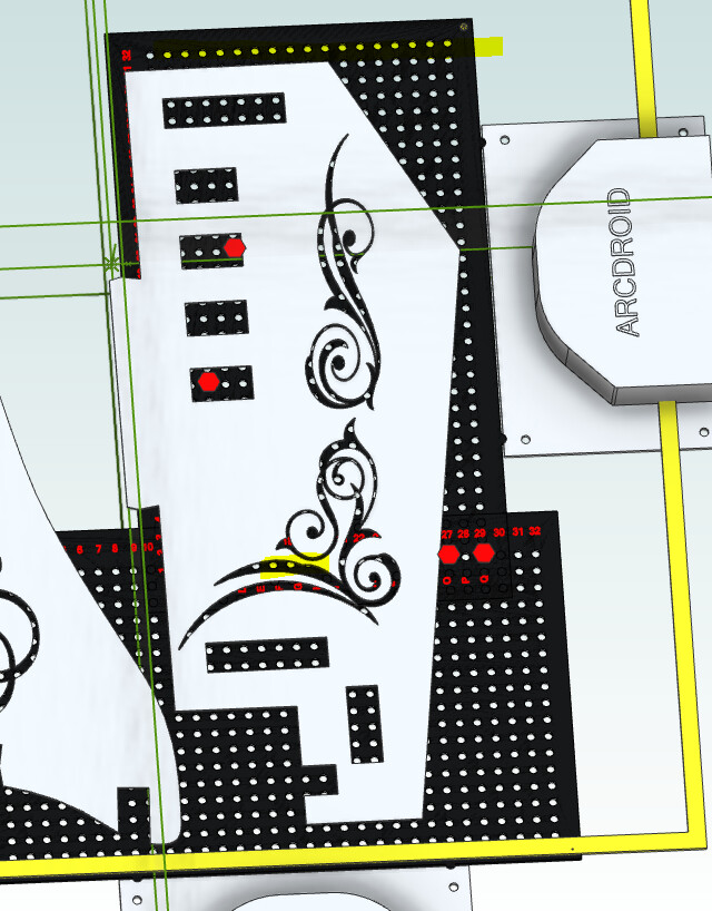
- I now hide the extrude work area and you can see that I have holes that align between the two and can use the letters/numbers as reference. In this case for cut 2 I would make a note of E25,H26 and when i moved the MIB for the second cut, I would place it and align the pins in those holes to the work piece.


Note that the cut area in yellow that represents the reference cut area isnt correct nor is the location of the Zero point but here is what the points to project should look like**
- Having noted your location holes it’s time to use “Project to Sketch” to project onto your work area surface 4 very important features. They are the two cut holes for the next reference points, the zero point so that in Fusion 360 you can set the local origin and in Alibre the yellow box which is a reference square. This square indicates the cut volume and when you go to export to your DXF, you will make this a regular sketch figure and use it to extrude cut out all the rest of the drawing but the area for the toolpaths for use in your Cam program.


- OK so now you will hide the first ArcDroid/MIB and repeat the steps for the subsequent cutting pieces by basically repeating from step 4 until you have covered your work area.

- Now that you have your completed: hole projects, origin points and cut out areas across your entire work area, you can then cycle through using cut and extrude to cut out an area and export to DXF. Then load into Fusion 360 for the normal steps for making Gcode. I will not repeat those here as ArcDroid has a good video to check out.
So as mentioned its a proof of concept and I encourage feedback and constructive criticism and ideas to improve it. Might also be nice for someone who is a Fusion 360 expert to see if they can recreate the idea.
I will be creating the MIB and trying it out as soon as my ArcDroid is fully set up and post more. thanks for reading.
Ken M.

